


Tweaking a Pro-Ject 6.1 Turntable
In February of 2000 I picked up a Sumiko Pro-Ject 6.1 Turntable badly in need of a new home. Though it was in bad shape it could be resurrected, and the low price made it attractive as a tweaking platform. I had been researching turntables for about three months when I bought it, as I had been lugging around a vinyl collection of some 150 albums since I sold by last turntable in 1991.
On various message boards whereon I lurk, the Pro-Ject was not heavily covered since most 'serious' analog junkies quickly move up to a Basis 1400, VPI, or Rega decks. But the few reviews I did find rated the Pro-ject well, with one even calling it 'a poor-mans Oracle'.
Turntable: Pro-Ject 6.1
Standard unit has a metal and glass platter with a felt mat. Currently using a sheet of
cork and rubber composition gasketing material between the glass and metal platters.
After buying the turntable I had to immediately order replacements for some missing parts (an anti-skate weight, a replacement damping rod, and an adjustment wrench for the tonearm bearings). With some trouble I was able to track down contacts for Sumiko in Berkeley, California and ended up talking to their head of enginering on the phone for almost 45 minutes. A very interesting fellow, he had some good advice about setting up the Pro-Ject tables with suspended subchassis':
- An isolated wall-mount or heavy floor-standing support stand will definitely improve the low-level dynamics.
- The subchassis suspension is critical and more complicated than it appears. It was designed as a system with the existing platter and tonearm load. Like the Linn LP-12 if you change the weight loading by much then the resonant frequencies will shift and the sound will degrade. Heavy Sorbothane platter mats are not good for this turntable!
- Set up the base to be absolutely level - there are three threaded cones under the base so this is pretty easy if the stand is anywhere close to level. Use a torpedo level to check this alignment.
- Adjust the screws at the top of the subchassis suspension springs with a junk record in place until the subchassis measures level.
- Check the compliance of the subchassis by pressing down on the record along the line where the stylus will track and observe that the subchassis rebounds freely and gently bounces at 2-3 Hertz (cycles per second).
- Set up the tonearm with a good tracking kit to get the correct overhang, azimuth, and vertical tracking angle (VTA).
- Check everything twice!
Disclaimer:
You can ruin your turntable with some of these tweaks if you screw up.
Follow all the suggestions of folks who are wiser than me and don't even try this if you don't know what you are attempting.
Take responsibility for your own actions and don't sue me, OK?
In this page:
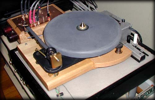
Mechanical Description
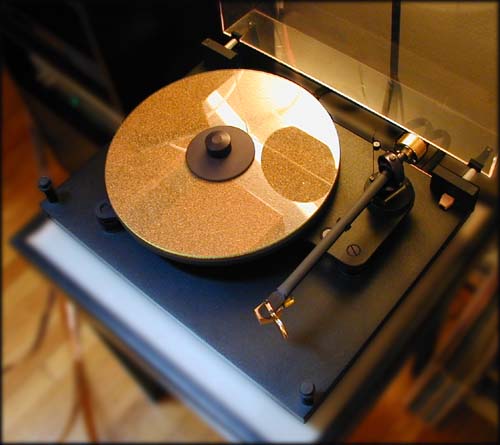
The Pro-ject 6.1, sadly no longer made, is a suspended-subchassis design with a thick aluminum plate joining the platter bearing and tonearm. This subchassis is supported by three tapered coil springs (the overall shape is tapered, not the spring wire itself) which are very carefully selected to provide the correct compliance under the weight of the platter, tonearm, and record. To dampen motion Sumiko has provided a fluid damping pot. This clear plastic pot is mounted to the base and filled with a clear viscous fluid. A thin adjustable brass rod is threaded into the bottom of the subchassis with a slotted head accessed from above once you remove the platter. This rod is adjusted to rest in the liquid with the full weight of the subchassis.
The subchassis springs in turn rest in three recesses in the solid MDF base, along with the motor, motor AC filter, and the RCA jacks for the tonearm signal lines. The base has three threaded cone feet for leveling and the subchassis has threaded posts at the top of each support spring for independant leveling.
The platter is die-cast zinc with balancing holes drilled on the bottom, with a 1/8 inch glass platter laid on top and a felt mat supplied, along with a record clamp. All of these platter parts rest on top of a sub-platter of ribbed injection molded structural foam with the threaded spindle attached. The platter components can be easily removed and the felt mat can be placed between the metal and glass platters for a different sound.
The medium-mass aluminum tonearm has an overhang of 220mm mounted in a double gimbal with adjustable sapphire bearings. The outside gimbal is mounted to a large hollow aluminum post which is clamped in place by 2 hex-key setscrews to provide vertical adjustment for VTA. The arm wand is an extruded aluminum tube of large diameter with one end flattened and cut to function as a headshell. The arm tube is attached with a screw at the top rear of the inner gimbal that can be loosened to adjust azimuth alignment (you must unscrew the anti-skate notched stub to reach the screw). Anti-skating force is provided by a counterweight hanging from a micro-filament and a post with three notches projecting from the rear of the inner gimbal. The support for the anti-skating weight is thin powder coated wire and must be adjusted to a particular position for optimum functioning.
The tonearm counterweight threads onto a plastic stub screwed onto the back of the arm tube assembly and has a fairly accurate dial indicator for weight. The counterweight stub has a rubber cushion for a compliant mount, and is stepped down about 1/16 inch to bring the center of gravity of the counterweight below the centerline of the arm tube.
The tonearm wires pass through the support post into a hollowed-out chamber beneath the rear corner and are soldered to gold-plated RCA jacks attached to a steel cover, along with a ground post attached by wires to the tonearm and subchassis.
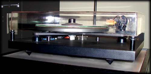
The dustcover mounts to hinges on the blocks at the back of the base and the front corners rest on two round posts. This arrangement is good-looking, but unfortunately provides a 1 1/2 inch gap around all four sides when the cover is closed; frequent cleaning is needed even with the cover closed.
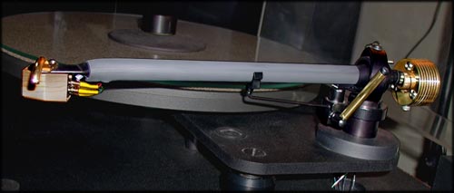
Tweaked Tonearm: Pro-Ject 6.1
Brass headshell lift, Custom rewire with Cardas tonearm wiring, Cardas cartridge clips,
Bronze Sleeve over new shoulderbolt for counterweight stub with Brass Counterweight, Grado Platinum cartridge.
Cork gasketing between glass and metal platters. Cosmetic brass trim over tonearm lift lever.
Tonearm
Adjust Bearings
Well, the bearings had some slop when I got the turntable, else I wouldn't have attempted this.
From Sumiko I got a neat little wrench for adjusting the cups - much easier to use than a pair of ring-pliers!
Test the bearings by grasping the arm tube and gently twisting back and forth; any clicking or movement
is a bad thing, but you don't want to tighten them too much and cause binding. It's a trial and error
process of adjusting, twisting, adjusting more. Finally, test the arm with the Hifi News and Record Reports
diagnostic album (a great tool!) to check the resonant frequency and for noise from binding.
An alternate method for checking bearing adjustment that I found later: Remove the arm and hold it by the base with the cartridge end hanging down, then pull the arm to one side and et it swing back and forth like a pendulum - count the swings to the settle point. Adjust the bearings and repeat. More swings = better adjustment, except if there is slop in the bearing you have gone too far...
Re-wiring the Tonearm
I rewired the arm with Cardas 30 gauge Litz wire running directly into half meter connection cables with no solder joints between the headshell and the RCA jacks at the phono preamp. I also used Cardas rhodium plated cartridge clips with no heavy splice wires between the clips and the inner arm wires - man, those wires are thin-thin-thin. While I was in there I also replaced the ground wires with teflon-insulated 28 gauge copper wires.
The process of rewiring is time consuming and involved.
Materials needed:
- 2 to 4 feet of 30 gauge stranded wire
(5 pieces - 1 red, 1 green, 1 blue, 1 white, 1 black. 2 feet to just replace the existing wires and use the RCA jacks, more for integral cables) - 4 new cartridge clips
- Silver-bearing solder
- Thin heat-shrink tubing
Process:
- Carefully remove the cartridge and put it in a safe place
- Clip the wires from the RCA jacks and ground post on the cover plate under the base, then loosen the arm post and remove the arm from the subchassis
- Unscrew the ground wire tab behind the headshell
- Pull the four cartridge wires out of the headshell, but NOT the ground wire
- Remove the rubber grommet behind the headshell around the hole into the arm tube (If you want to replace the counterweight stub, now is the time to remove the arm tube and access the screw holding it on from the inside of the inner arm gimbal)
- I braided the new signal wires together (red, green, blue, white) in a loose 4-cord square braid then attached them and the new ground wire (black) coming out of the post under the arm by making a loop in the ground wire and covering the twisted joint with a short piece of heatshrink
- Carefully pull the ground wire out from the headshell end of the arm tube. You may need to finesse the splice through the holes from the lower arm post and into the inner arm tube mount
- When the new wires are projecting from the headshell hole by about 1 1/2 inches remove the heatshrink and cut off the bent ends of the new wires
- Tape the wires in place to the headshell to prevent them sliding back into the tube!
- Replace the tonearm into the subchassis, sliding the new wires through the mounting collar at the base of the arm
- If you are going to use the existing RCA jacks (else, skip this step) cut off and strip the wires under the table and solder them to the RCA connectors. Skip the next two steps below...
- To terminate into integral cables, separate the channel signal lines and twist them together under the base (red and green for Right channel, blue and white for Left Channel). Remove the RCA jacks from the base cover plate
- Sleeve the wires with some dielectric (1/4 inch polyethylene tubing from Home Depot works well). Secure the ends of the sleeves under the base with tie-wraps and short screws (brass is non-magnetic)
- Attach the ground wires to the ground post on the base cover plate by soldering (best), by using crimped eyelets and a new threaded post (also good), or by a small twist-on wire nut (OK, not great)
- Screw the cover plate back into place, being very careful not to pinch any of the cables
- Cut off the signal wires at the headshell so that they are about 1 1/4 inches long and replace the rubber grommet in the arm tube
- Cut off the ground wire so it projects about 1/2 inch, strip the end, and solder on the small ground eyelet. Reattach the ground with the small screw behind the headshell
- Strip the four signal wires and solder on the new cartridge clips. This is much easier with a 'third hand' clamp to hold the wire and clip. Cut off 4 small pieces of shrinkwrap and shrink them over the joints for the cartridge clips
- Remount the cartridge and reset the tonearm weight. Check the cartridge azimuth and vertical tracking angle and then set the tonearm weight again. Set the cartridge overhang and then set the tonearm weight again
Adjust Headshell Angle
For some reason the headshell vertical angle was not aligned with the arm tube.
This meant that the arm had to be raised extremely high in the mounting collar to get the VTA correct,
and in this position the top tonearm bearing adjustment would contact the dustcover. Correcting this
was simple - clamp the headshell into a bench vise and gently bend the arm back slightly.
Adjust Dust Cover Height
To reduce problems with interferance with the tonearm I fitted some tubes to the rear
hinge rods to raise the rear of the cover, and found to rubber plumbing bushings that could fit
over the posts at the front.
Headshell Finger Lift
The original finger lift was lost before I bought the turntable, so I made a replacement
from half-round 1/8 inch brass stock from the hardware store. To match the brass 'theme'
I unscrewed the arm lift lever and sleeved it with a piece of brass tubing with foamed teflon
as a spacer (stripped from some Belden coax I had laying around). I chucked the old lift arm
into my drillpress and used a file on the spinning part to cut a step into the plastic knob
on the end to get a flush mount with the tubing.
The brass parts are easier to locate in dim light and makes the tonearm a little more custom.
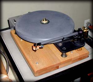
Heat-shrink Arm Tube Dampening
The grey arm tube in the picture above is a section of large-diameter black heat-shrink tubing applied.
This tubing reduces resonances in the tube without adding much weight.
Replace Counterweight
The original counterweight screwed onto the plastic counterweight stub but was not a rigid mount.
The Grado is a heavier cartridge and the weight was pretty far out on the stub; with the compliant stub
mount it drooped a little. I looked at several methods of replacement for the counterweight and stub,
but finally decided to stay with the existing stub since I didn't have access to machine tools needed
to make a new design. Instead, I sleeved the old stub with a plain bronze bearing with setscrews at the
front and rear and more foamed teflon for dampening and alignment.
The new counterweight design was a creature of convenience; a stack of large brass washers drilled and tapped for stainless steel 6-32 hex key screws, then 'turned' on my drillpress for truing and polishing. A single clamping bolt is used through a threaded hole on the bottom of the weight. Since the weight is made of washers it is easy to remove weight for a better match with lighter cartriges. The oversized hole through the center of the new counterweight brings the center of gravity down almost to the bottom of the arm tube.
But, the new weight requires a weight gauge for accurate use (recommend the Shure for US$20).
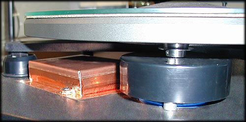
Tweaked Motor and AC Filter: Pro-Ject 6.1
Copper Shielding over AC filter and on motor under cover, vibration dampening under motor
(note O-ring under sub-chassis spring trim ring to raise it after shimming the springs),
rebuilt AC filter with shielded supply lines and switch lines,
replaced motor caps with Solen polypropylene film/foil,
12 ga solid-core braided 3-conductor power cord.
Motor and AC Filter Tweaks
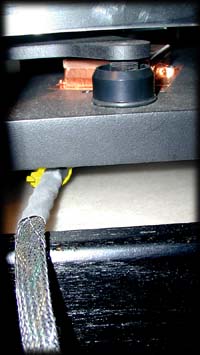
Replace Power Cord
The stock power cord for the turntable is a two conductor flat affair; a step up from
plain zip cord, but nothing special and the motor assembly is ungrounded to the wall outlet.
The 'Bottlehead special' is 12 gauge solid core braided - a tough procedure but worth it
as this is an inexpensive cord that really does sound better. I have a couple of spools of 12 ga
copper house wiring from Home Depot for this purpose so I cut off some wire and made up a custom cord
with a heavy-duty replacement plug and some black mesh cable covering I had taking up space in the closet.
This makes a great looking cable that is soldered directly to the motor filter circuitry.
I had to drill out the old access hole under the base to fit the larger cable into the motor filter box,
and then used a tiewrap for a strain relief.
AC Filter and RF Sheilding
The AC filter for the motor is a simple LC (inductor/capacitor) filter located in a box under the subchassis.
The motor has two pairs of thin wires connected here, and there is a power switch under the
left front corner connected to the filter with a piece of zip cord. None of these lines or
the filter itself are sheilded, which causes some hum with Grado cartridges (why Grado makes unsheilded
cartridges is another discussion).
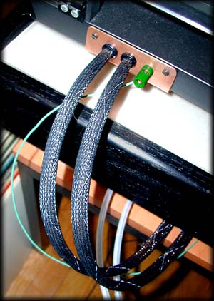
The filter components were unsoldered and remounted onto a terminal strip to be able to attach the larger power cable and switch wiring.
To shield the power assembly I started by fabricating a copper box for the filter covering the existing plastic filter box. The power switch lines were replaced with twisted 14 gauge solid core conductors with copper mesh shielding. Motor wires were twisted together in pairs and also shielded with copper mesh, soldered at the motor to the copper tape shielding and on the other end to the filter copper shielding. The filter box shield was soldered to the ground conductor.
Motor
The synchronus AC motor has a stamped steel case hidden under a black plastic cover.
Both are screwed to the base with machine screws into tall standoffs.
The motor has a thin felt washer under it to help isolate vibrations from the base.
I applied copper tape to the steel case and to the inside of the plastic cover and
grounded both to the filter assembly. The aluminum belt pulley is attached to the motor shaft
with a small setscrew and there is some height adjustment available on the shaft.
When I removed the motor I found that the plastic bearing cup hidden on the bottom of the case was cracked, but it wasn't expensive to replace the entire motor with a new one from Sumiko. This problem apparently can happen when the bottom of the platter smacks the top of the belt pulley mounted to the motor shaft. If you transport the turntable without removing the platter then you may be endangering this part!
Raise the Subchassis
When I originally set up the turntable I noticed that the bottom of the platter
would rub against the motor pulley when I pressed down slightly with a record cleaning brush as the
platter was turning - making a slight grinding sound. After futzing around with the setup I found
that the motor pulley was too high, even with it set as far down as practical. Rather than crank the
adjustment screws down in the subchassis and reduce the thread contact appreciably I decided to add
some washers between the base and springs (The turntable comes with thin metal blanks installed here anyway).
I glued several washers together with a thin coat of silicone gasketing RTV to prevent rattling,
and installed them in each spring well to raise the subchassis by around 3mm.
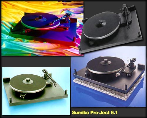
Found Images: Pro-Ject 6.1
Several of the small images found surfing reworked and assembled turntables.
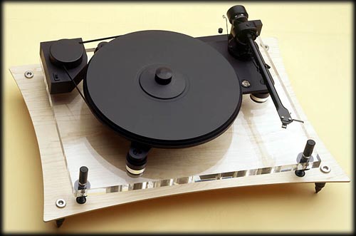
Pro_Ject Perspective
The Perspective replaced the Pro-Ject 6.9 in the Sumiko lineup.
It features the same subchasis as the 6.1 and 6.9 with an acrylic base.
Note new motor placement and acrylic/vinyl composite platter.
July 2002:
Maple base with cork center layer, oversized PVC platter, new brass tonearm weight,
and the motor mounted in separate box with lead/silicone weighting...
What's Next? 2002 Evolution
Now that I've pushed the basic design about as far as possible, it's time to begin fabricating parts! Now, if I only had time to finish all of the things I wanna do...
First, the platter. I weighed the OEM platter with a precision scale and made a replacement platter from some scrap PVC sheet cutoffs I bought. Since metal and glass are denser than polymer, the new platter will be thicker, and I can also make it an inch larger diameter to get more mass out to the circumference and increase the angular momentum at speed. To build this new platter I used glued-up sheets of grey PVC sheet cutoffs and profiled the platter using a jig and my router table. Unfortunately, though the PVC platter was thicker and larger in diameter, it was still outweighed by the metal and glass platter. So, remember the angular momentum rationale above? Not valid. To keep the same spring load for the suspension I bolted some heavy steel washers and neoprene spacers equidistant around the bearing through the aluminum subchassis so that the load had the same mass. The spring rate was unchanged and the bounce was still centered so this apparently worked.
Next, the base. This was primarily for aesthetics, but I built a new base from maple to match the cases I've made for my tube amps. The stock dust cover for the Pro-Ject is a little odd since it has a tall gap on all sides. I ended up junking the old cover and using a large chamois from a car wash accessories vendor instead - it works well and looks, well, interesting.
I looked at moving or replacing the motor so that hum interferance with the Grado cartridge was reduced. There are several possible DC motor conversions available, but I ended up going down another path since the hum was reduced when I moved the motor to the outboard pod made from a cast alloy box weighted with a mixture of lead shot and silicone sealant in a 2 cm layer across the bottom.
The tonearm lift causes the arm to move slightly to the outside when actuated. I tried to adjust the angle of the lift tab but was unsuccessful. The tab is screwed to the bottom of the arm tube so adjusting it usually just wrecks the azimuth of the headshell. I tried gluing a small piece of 400 grit sandpaper to the bottom of the lift tab, this helped a little.
Finally, I'm interested in the Origin Live RB250 tonearm conversion, which is universally lauded online. It looks like the overhang and weight specs are comparable with the stock Pro-Ject arm and it should be a simple swap. But, I'll have to give up the re-wiring job on the existing arm in the bargain. Eck.
But, in August 2002 I finally lost interest in the Pro-Ject and bought a 1960s-era Empire 208 off eBay. I'm working on another page to describe development of tweaks for that renovation... maybe I'll get that up in a few months. In the meantime here's a shot of the new turntable - it had to be machined to accept a modern tonearm (they have gotten longer over the years), so I drilled out the top plate and made an aluminum adapter for the Moth RB250 with Incognito re-wire and VTA adapter from Brit Audio. The arm also has an RB300 rear stub and an Expressimo 'Heavyweight', not shown below. The entire table was torn down and thoroughly cleaned, the wood base refinished, and a combination of damping materials was applied to the underside of the heavy cast aluminum top deck to reduce ringing. The aluminum alloy platter, a very nicely machined part, was treated with a silicate-loaded latex paint coating on the back.
These Empire turntables are built like tanks. Good old 1960's built-to-last American quality, we may never see it's like again. Heavy construction, a beautiful bearing and platter, a precision German Papst AC motor built to last 50 years, simple wiring and controls, and speed change via stepped pulley; plus it just sounds great. It has a low noise floor, pace, attack, a good soundstage. And people wig out when they find out how old it is.
I sold the Pro-Ject, tweaks and all, a couple of months after acquiring the Empire TT.
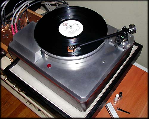
August 2002:
Empire 208 with Moth RB250 arm, RB300 stub and counterweight, Incognito wiring.
Links to Turntable Stuff
- Brit Audio Great deals on Rega tonarms and other British imports
- the Vinyl Asylum Great discussion area - use search!
- Sumiko
- Needle Doctor
- the Elusive Disc
- Music Direct
- Galen Carol Audio Friendly advice and good prices
- Elex Atelier The only good Empire replacement belts found so far...
- Atma-Sphere Empire 208 rebuild
- GWare's customized Empire turntables